BASIC TIMING TRAFIC CONTROL USING PIC16F877A
 |
| Figure 1: |
In this mini project we want to design a traffic light which goes through (red yellow green) sequence
The idea of this mini project is to show the basics of PICs.
Things needed
- PIC16F877A
- Crystal oscillator (any value)
- 22pf capacitors x2
- 9V transistor battery
- 7805 voltage regulator
- 220uF capacitor
- 10k resistor(R1)
- 220 ohms resistor x3
- LED (red, yellow, green)
Schematics diagram of the circuit
 |
| Figure 2: schematic diagram |
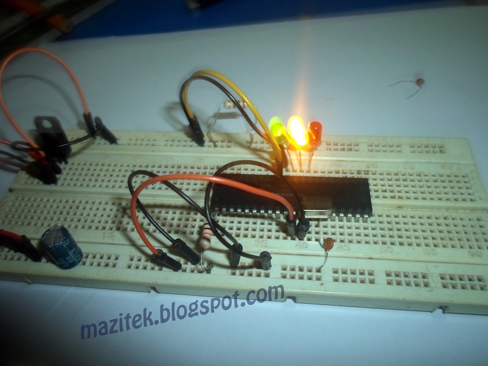
Breadboard circuit
 |
| Figure 3: circuit on breadboard |
Steps in the programming
MPLAB IDE from microchip was used to write the source code in C language and compiled with XC8 compiler from Microchip click here to download the IDE from Microchip- The configuration Crystal oscilator was used
- (WDTE) we don not want the microcontroller to reset itself for a given time interval hence WatchDog Timer(WDT) off.
- (PWTE) Allow a power up time delay by keeping CPU in reset state until the power supply becomes stable.
- (BOREN) when the microcontroller voltage supply below a required value; reset the microcontroler.
- (LVP) is used for low voltage In Circuit Serial Programming(ICSP) but we will not be using it.
- (CPD) is used to if you want to protect your EEPROM from being written to again.
- (WDT) is used to to protect your program memory from being written to again.
- (CP ) is used to protect the code on your program memory
NB: do not turn ON this configuration CPD, WDT and CP unless you are sure that the data on your RAM or ROM are final.To start with, we connect our LEDs to RD5,RD6, RD7 we used the #define directive to assign easy to remember words for the bits we connected our leds to. To access bits of PORTD we used PORTDbits.RDx where x is the bit number of PORTD. we then have to make PORTD an output port; this is done by using the TRISD register (TRISD=0x00), PORTD is an output port.
we create an endless loop using the while(1).
The XC8 compiler has inbuilt function for delay that is __delay_ms(x) but it can not exceed a certain limit depending on your Clock rate(frequency of oscillation ). hence we created two delay function using a for loop, one for seconds and the other for minutes.
The source code and the hex file can be downloaded by following the link given at the end of this page.
The hex file was then burn into the PIC with the help of PICKIT2 Replica I bought from Dealextreme
It has a ZIF socket where you can put your PIC inside and program it or connect used the ICSP version by connecting the pins to your microcontroller as shown below
 |
| Figure 4: using the ZIF socket to upload code to uC |
|
|


Final output


 |
| Figure 7: final output |
time, which means all of them cannot be on at a time so we can use one 220ohm
resistor for all the led by connecting them as shown below.
 |
| Figure 7: alternative for reduction of resistor if one LED comes at a time |
Note if you altering the design for other sequence in which two or more LEDs will be on at a time consider putting all the three 220ohm as shown in figure 2.
click to download the SOURCE CODE
click to download the SOURCE CODE
BASIC TIMING TRAFIC CONTROL USING PIC16F877A
 Reviewed by
Zakaria Mohammed
on
October 29, 2016
Rating:
Reviewed by
Zakaria Mohammed
on
October 29, 2016
Rating:
Reviewed by
Zakaria Mohammed
on
October 29, 2016
Rating:

No comments :